
Unmanned Aerial Vehicles (UAVs), also known as drones, have brought in new vitality to surveying and mapping. Drones bring in more accuracy and quality with cost and time efficiency. Using drones in surveying also eliminates the need for humans to physically access hard-to-reach and dangerous terrains. It would not be incorrect to say, drones make surveying and mapping more efficient, profitable, and safe.
Due to these benefits, drones are being increasingly used for commercial purposes and a sector that is seeing its increased use is the transportation engineering field. UAVs are used as a virtual surveying tool to collect aerial footage and create 3D maps. These maps assist in designing transportation infrastructure and reviewing current infrastructure. This method of creating a 3D model is less expensive and faster than other traditional surveying methods.
We get to witness the benefits first-hand as we explore a specific project where a company, specializing in ropeway engineering and transportation systems commissioned AAM India to conduct two topographical surveys of an area that stretched across Barasanka and Uperkaipadar. AAM utilised a drone to complete these surveys and provide ortho images, a topographical map with contour details as well as point cloud data. These surveys enabled a mining transportation system to be successfully designed and constructed and therefore paved the way for mining operations in the area to eventually begin.
What were the survey requirements?
For initiating mining operations in the area stretching across Barasanka and Uperkaipadar, a mining transportation system called the RopeCon system had to be built. In order to build this, the company needed two types of survey data.
Firstly, survey data for carrying out the engineering and design of the system. The final route and tower locations were defined with this survey. It included corridor width along the line 300 – 400 m (from centre line 150 – 200 m to the left and right side) and 2 m distance of contour lines. The relative accuracy to ground was 10 cm approximate.
Secondly, the project required survey data for planning the construction of the system. The foundation design and final construction details were to be defined with this survey. It included corridor width along the line 10 – 20 m (from centre line 5 – 10 m to the left and right side) and the area around tower locations, 30 – 40 m from centre point and 1 m distance of contour lines. The relative accuracy to ground was 10 cm approximate.
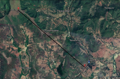
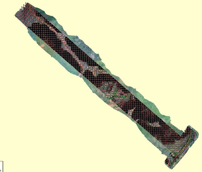
The Area of Interest so identified was as shown below.
?
How did AAM plan the work?
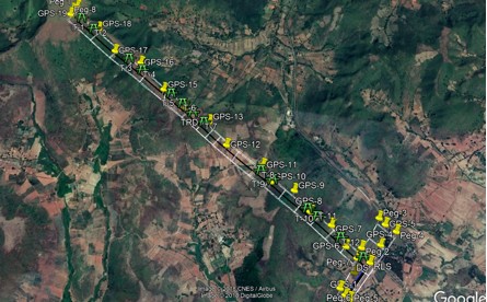
The work started with GCP – Pre- Marking. The GCP was visible and painted with a white background and black foreground.
The UAV used by AAM for the survey was DJI Phantom 4 Pro (Rotary) with flying height of 200 to 250 feet (as per the regulation by DGCA). It produced JPG Images with GPS/IMU (EXIF).
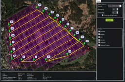
Drone mission and flight planning
For the whole survey, AAM planned for 23 flights based on the area, with a flexible schedule depending on the geographical area.
Output from the Drone Survey
The final topographical map data produced by the UAV included details of all features such as median, carriageway, paved shoulders, earthen shoulders, structures (bridges, culverts etc.), retaining structures edges/ offset & levels, anti-crash barriers, railings, drains; edges of the drains with invert & top levels, utilities, existing service roads, cross roads, cart tracks, electric and telephone installations (both O/H as well as underground), huts, buildings, wells, shops, fencing etc. falling within the extent of survey.
In the final drawing, AAM provided:
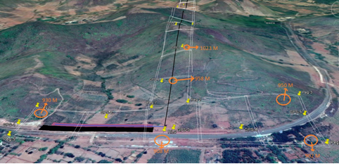
Height of the vegetation
Other obstacles that needed to be crossed
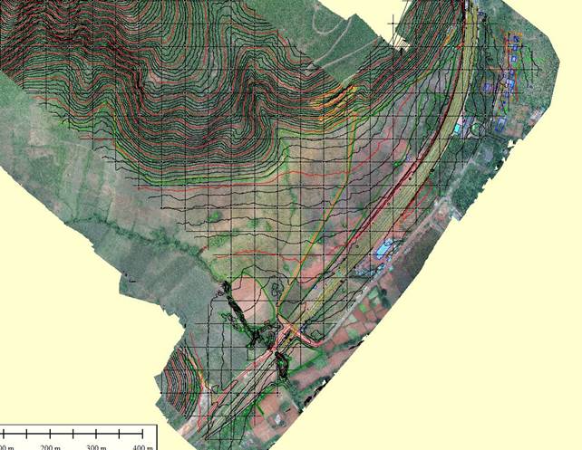
1 m and 2 m contour maps for two scopes
Utilities like electric line, high tension line, transformer and underground lines such as OFC, gas line, etc. along the proposed ROW were done mentioning its ownership, Dia/voltage and vertical clearance available above proposed road level
Existing drainage lines, top & invert level along with width & typical cross section details
All specified features were presented in the final drawings in accordance with the styles and layers specified. Survey points and features were annotated with text including feature name, elevation, plan position, point number, survey notes etc. AAM also submitted a survey report with the drawings.
The detailed survey data obtained through the drone survey led to the designing of a robust mining transportation system, which allowed mining to take place seamlessly in the area.
Tags: Surveying, Drone Photography, Mining
Get some quotes for a drone operator
✔ 100% free service✔ Featured in the SMH, The Age & WA Today
✔ 1,800+ online recommendations